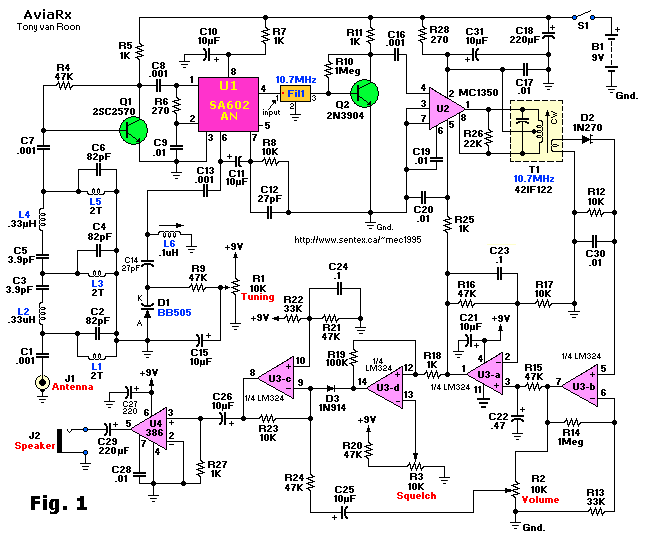
#All band receiver radio circuit how to#
With any luck, you might be able to find an old portable radio or clock radio that uses a TDA7000-type chip, and figure out how to inject a CV into the varactor to forcibly tune it.

If you can find a TDA7000 family chip, they can be set up for use with a varactor diode. The SL ones are more self-contained and don't need much outboard componentry. Silicon Labs makes similar devices, intended for microprocessor control, which seems to be the way they're all headed. They usually need external IF transformers and an RF tank circuit too, so they're not easy for a DIYer to use. (Look it up.) Those parts are obsolete and difficult to find.īut most of the modern ones use digital frequency synthesis. Rod Serling Fan Club wrote:I think the main point of having a radio module, aside from just using a commercially available radio, is if it had CV to scan the stations.Īnalog FM-radio receiver chips used to have CV inputs for tuning control, as they simply used a varactor diode. Perhaps now I can go back to lurking and wait for someone to design the module I'm looking for. I've explained why I'm only interested in SW and I've apologised for mixing up up the terms. This has nothing to do with a radio module. It'll remain as weird and interesting post-switchover as always has. I don't care about that - I just want to know what the spectrum will sound like when it goes digital, and nobody's talking about that. It's hard to find any real technical details amoungst all the search hits for the switchover politics. I've not read or heard any details about how digital comms use radio, so I don't know what size those gaps would be.

Maybe there'll be some gaps in the spectrum that we can use for noise sources. The UK radio switchover is set to begin in 2015. I was trying to be consistant with terms already being used, so.oh well. However, I do apologise for mixing up the terms. SW is, as the name suggests, an extreme end. The performance of all circuits and their applications is verified using PSPICE simulation program with 0.25μ CMOS technology.I was mostly talking about frequency bands. Current conveyors are considered one of the best candidates as a basic building block for communication systems which include filters, variable gain amplifiers and square/triangular wave generators. Each type suits certain applications with specific terminal characteristic requirements either differential or single ended. By virtue of the efforts that have been conducted, the current conveyor types finally can be realized using CMOS technology. In this research five current conveyor types are presented in order to deeply understand DVCC. Besides, DVCC supports differential input systems which increase the immunity to noise, resulting in improved received signal. However, Current mode Differential Voltage Current Conveyor (DVCC) was able to redress this drawback by its ability to provide constant bandwidth for different gains. simple circuit deigns schemes but it can’t handle high frequency communication applications. Most analog systems are implemented using operational amplifier. The development in CMOS technology serves widely in this direction. Thus, the manufacturers are going forward to meet the mentioned specifications by developing efficient device architecture.

Most common communication devices are small but have high quality of services and low power consumption to protect user’s health. To provide some background, Section II presents general expressions of the linearity metrics of a single-stage system as a function of DC parameters. The goal of this work is to characterize quantitatively the linearity of sub-micron CMOS devices using widelyknown metrics such as 1dB compression and 3rd-orderintermodulation intercept points. However, the equally important issue of linearity is not well studied. As CMOS technology scales into the sub-micron regime, issues such as excess thermal noise due to hot electron e#ects have been well documented #2#. Introduction R ADIO frequency designs in CMOS are increasingly being explored to take advantage of rapid technology advances. In particular, the linearity of short-channel MOSFETs is examined. These two #gures of merit measure the linearity of a system.

This paper presents analytical expressions for the 1dB compression and third-order intercept points as a function of DC-bias and technology parameters.


 0 kommentar(er)
